xilinx fpga发展路线图(XilinxXC7Z020双核ARMFPGA开发板试用合集)
分享产品试用报告,测试板卡是基于Xilinx Zynq-7000系列XC7Z010/XC7Z020高性能低功耗处理器设计的异构多核SoC工业级核心板。

Petalinux制作linux系统1配置
基本配置信息如下:
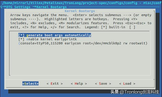
(1) 配置启动项

(2) 配置SD卡分区

(3) 首选SD启动设置

(4) 主机名设定

2文件系统配置
主要包括如下:
(1) gcc编译支持

(2) python支持

3 设备树
另一个一个最重要的就是编写设备树文件,主要包括LED以及按键的设备树和axi_uart16550设备树文件的编写,内容如下:
/include/ "system-conf.dtsi"
/ {
aliases{
ethernet0= &gem0;
serial0= &uart1;
};
gpio-keys{
compatible = "gpio-keys";
#gpio-cells = <2>;
SW0 {
label= "SW0";
#gpio-cells= <2>;
gpios= <&axi_gpio_1 0x0 0x0 0x0>;
linux,code= <108>;
gpio-key,wakeup;
autorepeat;
};
SW1 {
label= "SW1";
#gpio-cells= <2>;
gpios= <&axi_gpio_1 0x1 0x0 0x0>;
linux,code= <108>;
gpio-key,wakeup;
autorepeat;
};
SW2 {
label= "SW2";
#gpio-cells= <2>;
gpios= <&axi_gpio_1 0x2 0x0 0x0>;
linux,code= <108>;
gpio-key,wakeup;
autorepeat;
};
};
gpio-leds{
compatible= "gpio-leds";
#gpio-cells= <2>;
led-ld0{
label= "led-ld0";
#gpio-cells= <2>;
gpios= <&axi_gpio_0 0x0 0 0x0>;
default-state= "on";
linux,default-trigger= "default-on";
};
led-ld1{
label= "led-ld1";
#gpio-cells= <2>;
gpios= <&axi_gpio_0 0x1 0 0x0>;
default-state= "on";
linux,default-trigger= "default-on";
};
led-ld2{
label= "led-ld2";
#gpio-cells= <2>;
gpios= <&axi_gpio_0 0x2 0 0x0>;
default-state= "on";
linux,default-trigger= "default-on";
};
};
};
&axi_uart16550_0 {
status= "okay";
port-number= <1>;
current-speed= <57600>;
xlnx,use-modem-ports= <0x0>;
xlnx,use-user-ports= <0x0>;
};
&axi_uart16550_1 {
status= "okay";
port-number= <1>;
current-speed= <57600>;
xlnx,use-modem-ports= <0x0>;
xlnx,use-user-ports= <0x0>;
};
实验
启动界面如下:
Boot

Kernel

登录

从上述界面可知,linux系统启动成功,输入密码和账户名即可。
1查看各项驱动
(1) gpio驱动

(2) uart 16550驱动

从上述信息可知成功启动了相应驱动。
2 MIO LED实验
该实验的LED实验情况如下:

实验现象如下:

代码如下:
#include <stdio.h>
#include <fcntl.h>
#include <stdlib.h>
#include <unistd.h>
int main()
{
int value;
int export;
int direction;
//export GPIO controller
export = open("/sys/class/gpio/export", O_WRONLY);
if(export < 0)
{
printf("Cannot open GPIO controller export\n");
exit(1);
}
write(export, "909", 4);
close(export);
printf("GPIO controller export successfully\n");
//Modify GPIO controller direction
direction = open("/sys/class/gpio/gpio909/direction",O_WRONLY);
if(direction < 0)
{
printf("Cannot open GPIO controller direction\n");
exit(1);
}
write(direction, "out", 4);
close(direction);
printf("GPIO controller direction changed to outputsuccessfully\n");
// Modify GPIO controller value
value = open("/sys/class/gpio/gpio909/value", O_RDWR);
if(value < 0)
{
printf("Cannot open GPIO controller value\n");
exit(1);
}
//Swap GPIO control value each 1 second
while (1)
{
sleep(1);
write(value,"1", 2);
printf("GPIO controller value changed to 1 successfully\n");
sleep(1);
write(value,"0", 2);
printf("GPIO controller value changed to 0 successfully\n");
}
}
3 axi gpio led实验
该实验情况如下:

实验如下:

代码如下:
#include <stdio.h>
#include <fcntl.h>
#include <stdlib.h>
#include <unistd.h>
int main()
{
int led0;
int led1;
int led2;
//export GPIO controller
led0 = open("/sys/class/leds/led-ld0/brightness", O_WRONLY);
led1 = open("/sys/class/leds/led-ld1/brightness", O_WRONLY);
led2 = open("/sys/class/leds/led-ld2/brightness", O_WRONLY);
if(led0 < 0 | led1 < 0 | led2 < 0)
{
printf("Cannot open GPIO controller export\n");
exit(1);
}
write(led0,"0", 2);
write(led1,"0", 2);
write(led2,"0", 2);
//Swap GPIO control value each 1 second
while (1)
{
sleep(1);
write(led0,"255", 4);
sleep(1);
write(led1,"255", 4);
sleep(1);
write(led2,"255", 4);
printf("GPIO controller value changed to 1 successfully\n");
sleep(1);
write(led0,"0", 2);
sleep(1);
write(led1,"0", 2);
sleep(1);
write(led2,"0", 2);
printf("GPIO controller value changed to 0 successfully\n");
}
}
4 uart16550实验
根据上述信息可知,串口的驱动字符名为ttyS1和ttyS2,因此实验现象如下:

免责声明:本文仅代表文章作者的个人观点,与本站无关。其原创性、真实性以及文中陈述文字和内容未经本站证实,对本文以及其中全部或者部分内容文字的真实性、完整性和原创性本站不作任何保证或承诺,请读者仅作参考,并自行核实相关内容。文章投诉邮箱:anhduc.ph@yahoo.com


